前回は、ESP32とST7735を使って、画像のディスプレイ描画を行いました。
今回は以下の記事の「魔法の絵画」のプロトタイプを作るために、 ST7735のTFT液晶ディスプレイを2枚使用し、画像の描画とアニメーション描画を行ってみます。

この記事は以下の2部構成になっています。
- 複数ディスプレイへの画像表示
- アニメーションの実装
1. 複数ディスプレイへの画像表示
まず、2枚のST7735ディスプレイに同じ画像を表示するプログラムを作成します。
1.1 必要なライブラリ
以下のライブラリを使用します。
[dependencies]
log = { version = "0.4", default-features = false }
esp-idf-svc = { version = "0.49", default-features = false }
esp-idf-hal = "0.44.0"
esp-idf-sys = "0.35.0"
anyhow = "1.0.86"
embedded-hal = "1.0.0"
embedded-graphics = "0.8.1"
st7735-lcd = "0.10.0"
tinybmp = "0.6.0"
1.2 ピン設定
ESP32と2つのST7735ディスプレイを以下のように接続します。
| ST7735 LCD ピン | ESP32 GPIO (Display 1) | ESP32 GPIO (Display 2) | 機能 |
|---|---|---|---|
| SCK | GPIO18 | GPIO18 (共通) | SCLK |
| SDA | GPIO23 | GPIO23 (共通) | MOSI |
| A0 | GPIO16 | GPIO17 | DC |
| RESET | GPIO4 | GPIO5 | RST |
| CS | GPIO15 | GPIO21 | CS |
| GND | GND | GND | グラウンド |
| VCC | 3.3V | 3.3V | 電源 |
| LED | 3.3V | 3.3V | バックライト |
1.3 コード解説
以下、複数ディスプレイに画像を表示するコードを示します。
use embedded_graphics::image::Image;
use embedded_graphics::pixelcolor::Rgb565;
use embedded_graphics::prelude::*;
use esp_idf_hal::delay::FreeRtos;
use esp_idf_hal::gpio::{AnyIOPin, PinDriver};
use esp_idf_hal::prelude::Peripherals;
use esp_idf_hal::prelude::*;
use esp_idf_hal::spi;
use esp_idf_hal::spi::SpiDriver;
use st7735_lcd;
use st7735_lcd::ST7735;
use tinybmp::Bmp;

const BITMAP_DATA: &[u8] = include_bytes!("../resources/image.bmp");

fn main() -> anyhow::Result<()> {
    esp_idf_sys::link_patches();
    esp_idf_svc::log::EspLogger::initialize_default();

    let peripherals = Peripherals::take()?;

    // ピンの設定
    let spi = peripherals.spi2;
    let sclk = peripherals.pins.gpio18;
    let sdo = peripherals.pins.gpio23;
    let rst1 = PinDriver::output(peripherals.pins.gpio4)?;
    let rst2 = PinDriver::output(peripherals.pins.gpio5)?;
    let dc1 = PinDriver::output(peripherals.pins.gpio16)?;
    let dc2 = PinDriver::output(peripherals.pins.gpio17)?;
    let cs1 = peripherals.pins.gpio15;
    let cs2 = peripherals.pins.gpio21;

    // SPIドライバーの設定
    let driver_config = Default::default();
    let spi_config = spi::SpiConfig::new().baudrate(20.MHz().into());
    let spi_driver = SpiDriver::new(spi, sclk, sdo, None::<AnyIOPin>, &driver_config)?;

    let spi_device1 = spi::SpiDeviceDriver::new(&spi_driver, Some(cs1), &spi_config)?;
    let spi_device2 = spi::SpiDeviceDriver::new(&spi_driver, Some(cs2), &spi_config)?;

    // ディスプレイの設定
    let rgb = false;
    let inverted = false;
    let width = 128;
    let height = 128;

    let mut delay = FreeRtos;

    let mut display1 = ST7735::new(spi_device1, dc1, rst1, rgb, inverted, width, height);
    let mut display2 = ST7735::new(spi_device2, dc2, rst2, rgb, inverted, width, height);

    // ディスプレイの初期化
    display1.init(&mut delay).unwrap();
    display1.clear(Rgb565::BLACK).unwrap();
    display1.set_offset(0, 0);

    display2.init(&mut delay).unwrap();
    display2.clear(Rgb565::BLACK).unwrap();
    display2.set_offset(0, 0);

    // BMPデータの読み込み
    let bmp = Bmp::from_slice(BITMAP_DATA).unwrap();
    let image = Image::new(&bmp, Point::zero());

    // それぞれのディスプレイに描画
    image.draw(&mut display1).unwrap();
    image.draw(&mut display2).unwrap();

    println!("The screen should display the bitmap image.");
    loop {
        FreeRtos::delay_ms(1000);
    }
}
コードの解説
-
SPI設定: 1つのSPIバスを2つのディスプレイで共有しています。
SpiDriverを作成し、それを基に2つのSpiDeviceDriverを初期化しています。 -
ピン設定: 各ディスプレイに対して個別のRST(リセット)、DC(データ/コマンド)、CS(チップセレクト)ピンを設定しています。
-
ディスプレイ初期化: 2つのディスプレイオブジェクトを作成し、それぞれ初期化しています。
-
画像描画: 1つのBMPファイルを読み込み、両方のディスプレイに同じ画像を描画しています。
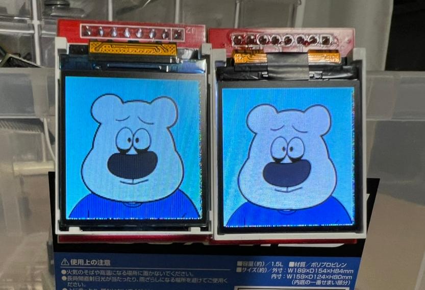
1.4 複数表示の動作
以下の通り、2枚のディスプレイに画像が表示されました。
2. アニメーション表示
次に、複数の画像を順番に表示してアニメーション効果を作り出します。
2.1 コード解説
以下、アニメーションを実装するコードを示します。
use std::collections::HashMap;
use embedded_graphics::image::Image;
use embedded_graphics::prelude::*;
use esp_idf_hal::delay::FreeRtos;
use esp_idf_hal::gpio::{AnyIOPin, PinDriver};
use esp_idf_hal::prelude::Peripherals;
use esp_idf_hal::prelude::*;
use esp_idf_hal::spi;
use esp_idf_hal::spi::SpiDriver;
use st7735_lcd;
use st7735_lcd::ST7735;
use tinybmp::Bmp;

const CAT_1: &[u8] = include_bytes!("../resources/eye/cat-1.bmp");
const CAT_2: &[u8] = include_bytes!("../resources/eye/cat-2.bmp");
const CIRCLE_1: &[u8] = include_bytes!("../resources/eye/circle-1.bmp");
const CIRCLE_2: &[u8] = include_bytes!("../resources/eye/circle-2.bmp");
const CIRCLE_3: &[u8] = include_bytes!("../resources/eye/circle-3.bmp");
const EYE_1: &[u8] = include_bytes!("../resources/eye/eye-1.bmp");
const EYE_2: &[u8] = include_bytes!("../resources/eye/eye-2.bmp");
const EYE_3: &[u8] = include_bytes!("../resources/eye/eye-3.bmp");
const HEART_1: &[u8] = include_bytes!("../resources/eye/heart-1.bmp");
const HEART_2: &[u8] = include_bytes!("../resources/eye/heart-2.bmp");
const HEART_3: &[u8] = include_bytes!("../resources/eye/heart-3.bmp");
const HEART_4: &[u8] = include_bytes!("../resources/eye/heart-4.bmp");
const TEAR_1: &[u8] = include_bytes!("../resources/eye/tear-1.bmp");
const TEAR_2: &[u8] = include_bytes!("../resources/eye/tear-2.bmp");
const TEAR_3: &[u8] = include_bytes!("../resources/eye/tear-3.bmp");
const TEAR_4: &[u8] = include_bytes!("../resources/eye/tear-4.bmp");

fn main() -> anyhow::Result<()> {
    esp_idf_sys::link_patches();
    esp_idf_svc::log::EspLogger::initialize_default();

    let peripherals = Peripherals::take()?;

    // ピンの設定
    let spi = peripherals.spi2;
    let sclk = peripherals.pins.gpio18;
    let sdo = peripherals.pins.gpio23;
    let rst1 = PinDriver::output(peripherals.pins.gpio4)?;
    let rst2 = PinDriver::output(peripherals.pins.gpio5)?;
    let dc1 = PinDriver::output(peripherals.pins.gpio16)?;
    let dc2 = PinDriver::output(peripherals.pins.gpio17)?;
    let cs1 = peripherals.pins.gpio15;
    let cs2 = peripherals.pins.gpio21;

    // SPIドライバーの設定
    let driver_config = Default::default();
    let spi_config = spi::SpiConfig::new().baudrate(20.MHz().into());
    let spi_driver = SpiDriver::new(spi, sclk, sdo, None::<AnyIOPin>, &driver_config)?;

    let spi_device1 = spi::SpiDeviceDriver::new(&spi_driver, Some(cs1), &spi_config)?;
    let spi_device2 = spi::SpiDeviceDriver::new(&spi_driver, Some(cs2), &spi_config)?;

    // ディスプレイの設定
    let rgb = false;
    let inverted = false;
    let width = 128;
    let height = 128;

    let mut delay = FreeRtos;

    let mut display1 = ST7735::new(spi_device1, dc1, rst1, rgb, inverted, width, height);
    let mut display2 = ST7735::new(spi_device2, dc2, rst2, rgb, inverted, width, height);

    // ディスプレイの初期化
    display1.init(&mut delay).unwrap();
    display2.init(&mut delay).unwrap();

    // 画像データをカテゴリごとにグループ化
    let mut image_categories = HashMap::new();
    image_categories.insert("tear", vec![TEAR_1, TEAR_2, TEAR_3, TEAR_4]);
    image_categories.insert("cat", vec![CAT_1, CAT_2]);
    image_categories.insert("circle", vec![CIRCLE_1, CIRCLE_2, CIRCLE_3]);
    image_categories.insert("eye", vec![EYE_1, EYE_2, EYE_3]);
    image_categories.insert("heart", vec![HEART_1, HEART_2, HEART_3, HEART_4]);

    let category_order = ["tear", "cat", "circle", "eye", "heart"];

    loop {
        for &category in &category_order {
            let images = image_categories.get(category).unwrap();

            // 各カテゴリを5周表示
            for _ in 0..5 {
                for &image_data in images {
                    // BMPデータの読み込み
                    let bmp = Bmp::from_slice(image_data).unwrap();
                    let image = Image::new(&bmp, Point::zero());

                    image.draw(&mut display1).unwrap();
                    image.draw(&mut display2).unwrap();

                    // 0.5秒待機
                    FreeRtos::delay_ms(500);
                }
            }
        }
    }
}
-
画像データの管理: 複数の画像をカテゴリごとで
HashMapで管理しています。 -
アニメーションループ: カテゴリごとに画像を順番に表示し、各カテゴリを10回繰り返しています。
-
表示間隔: 各画像の表示間隔を0.8秒に設定しています。
-
両ディスプレイへの同時描画: 同じ画像を両方のディスプレイに同時に描画しています。
各カテゴリのアニメーションが10回ずつ繰り返され、その後次のカテゴリに移ります。 ただし今回の実装だと左右の描画処理に一瞬ずれがあるので、完全に同時にしたい場合は対策する必要があります。
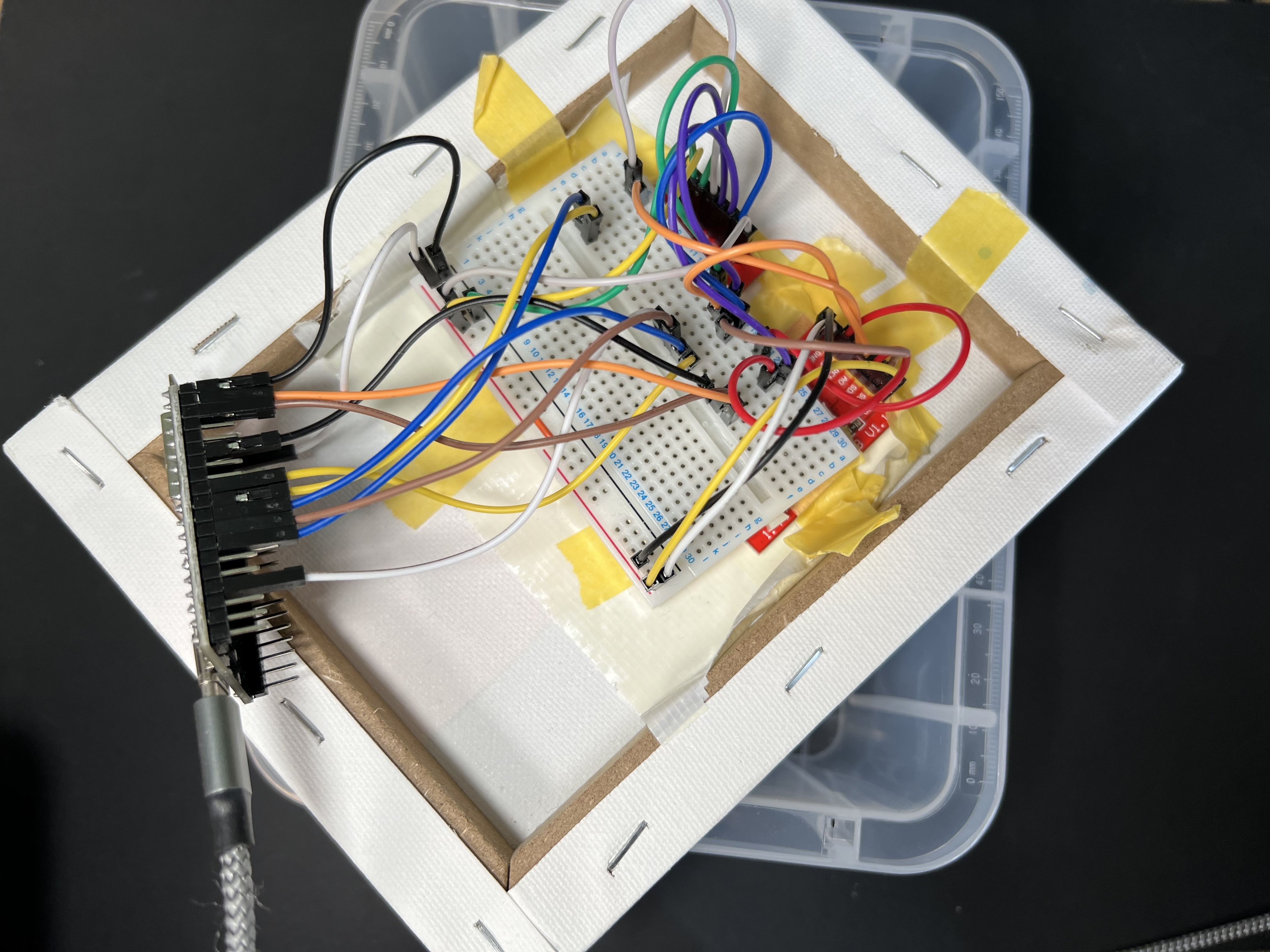
2.2 配線
マスキングテープで貼り付けてます。(雑すみません)
2.3 アニメーションの動作
実際の動作は以下の通りになりました。